Canterbury Christ Church University

Networking - OSI and IPv4

Course Code: U19952

Course Name: Fundamentals of Computer Systems

Credits: 20

Module Leader: Ali Jaddoa
Fundamental of Computer Systems: U19952-2023-2024
Canterbury Christ Church University

Source to Destination Delivery

Fundamental of Computer Systems: U19952-2023-2024
Canterbury Christ Church University

Source to Destination Delivery

Fundamental of Computer Systems: U19952-2023-2024
Canterbury Christ Church University

What is the Open Systems Interconnection (OSI) Model?

  • OSI model describes seven layers that computer systems use to communicate over a network.
  • Introduce in 1983 by US DoD and adopted by the ISO standards in 1984​

width:1OO% center

​​

Fundamental of Computer Systems: U19952-2023-2024
Canterbury Christ Church University

The Seven Layers of the Open Systems Interconnection Model

Mnemonics

Top to bottom

  • Australia Post Sucks They Never Deliver Parcels
  • All People Seem To Need Data Processing​
  • All People Should Try New Dr Pepper​
  • Aristotle Plato Socrates Three Noble Distinguished Philosophers

Bottom to Top

  • Please Do Not Teach Students Pointless Acronyms
  • Please Do Not Throw Sausage Pizza Away
  • Please Do Not Touch Steve's Pet Alligator
Fundamental of Computer Systems: U19952-2023-2024
Canterbury Christ Church University
Fundamental of Computer Systems: U19952-2023-2024
Canterbury Christ Church University

Layer-7: Application Layer

  • This is the layer that most users interact with and will recognise.

  • Provides network services to the end user. ​

  • These services are protocols that work with the data the client is using. HTTP, HTTPS etc that is used with web browsers such as Google Chrome, Firefox, and Internet Explorer.​

  • Other examples of applications that use this layer are Office, Outlook, and Skype.​

Fundamental of Computer Systems: U19952-2023-2024
Canterbury Christ Church University

Layer-6: Presentation Layer

  • Syntax processing or converting data from one format to another.​

  • This layer handles translating the data from the top layer, which is presented in application format, to network format and vice versa.​

  • After the Presentation layer processes the data from one format to another, the information is then passed to the Session layer or the Application layer depending on whether the data is transmitting or receiving​

Fundamental of Computer Systems: U19952-2023-2024
Canterbury Christ Church University

Layer-5: Session Layer

  • The construction, direction, and conclusion of connections between devices occur. ​

  • This layer supports multiple types of connections as well as being responsible for authentication and reconnection if a network interruption should occur.​

  • After the session is established the data then passes to or from the Transport layer​

Fundamental of Computer Systems: U19952-2023-2024
Canterbury Christ Church University

Layers-4: Transport Layer

  • Transmission of data across network connections​

  • Coordinates how much data to send, how fast, where it goes, and these sort of things. ​

  • Services may be provided by TCP and “User Datagram Protocol” or UDP. Other protocols may provide additional capabilities including error recovery, data flow, and retransmission.​

Fundamental of Computer Systems: U19952-2023-2024
Canterbury Christ Church University

Layer-3: Network Layer

  • Handles the routing of data​

  • Each frame of data is examined to conclude if the data has reached its ultimate target. ​

  • Sends data to the correct destination on transmitted and received transmissions ​

  • The IP portion of Transmission Control Protocol /Internet Protocol (TCP/IP) is the commonly known network layer for the Internet.​

Fundamental of Computer Systems: U19952-2023-2024
Canterbury Christ Church University

Layer-2: Data Link

  • Establishes and terminates a connections ​

  • Frames ​

  • Logical Link Control (LLC), which identifies ​network protocols, performs error checking and synchronizes frames​

  • Media Access Control (MAC) which uses ​MAC addresses to connect devices and ​
    define permissions to transmit and receive data.​

Fundamental of Computer Systems: U19952-2023-2024
Canterbury Christ Church University

Layers-1: Physical

  • Physical cable between network nodes​

  • Wireless connection between network nodes ​

  • Connector, the ​electrical cable or ​wireless technology ​

  • Transmission of the raw data packets ​0s and 1s,​

  • Control of bit rate​

  • Electrons, RF or Light​

Fundamental of Computer Systems: U19952-2023-2024
Canterbury Christ Church University

Advantages of the OSI Model

The OSI model helps users and operators of computer networks:​

  • Determine the required hardware and software to build their network​

  • Understand and communicate the process followed by components communicating across a network​

  • Perform troubleshooting, by identifying which network layer is causing an issue and focusing efforts on that layer​

Fundamental of Computer Systems: U19952-2023-2024
Canterbury Christ Church University

Advantages of the OSI Model

The OSI model helps network device manufacturers and networking software vendors:​

  • Create devices and software that can communicate with products from any other vendor, allowing open interoperability​

  • Define which parts of the network their products should work with.​

  • Communicate to users at which network layers their product operates – for example, only at the application layer, or across the stack.

Fundamental of Computer Systems: U19952-2023-2024
Canterbury Christ Church University

OSI In Action Example 1

Fundamental of Computer Systems: U19952-2023-2024
Canterbury Christ Church University

OSI In Action Example 2

Fundamental of Computer Systems: U19952-2023-2024
Canterbury Christ Church University

TCP/IP Layer Stack Model

Fundamental of Computer Systems: U19952-2023-2024
Canterbury Christ Church University

TCP/IP vs OSI

  • The main difference is that OSI is a conceptual model that is not practically used for communication. Rather, it defines how applications can communicate over a network. ​

  • TCP/IP, on the other hand, is widely used to establish links and network interaction.​

  • The TCP/IP protocols lay out standards on which the internet was created, ​

  • While the OSI model provides guidelines on how communication has to be done. Therefore, TCP/IP is a more practical model​

Fundamental of Computer Systems: U19952-2023-2024
Canterbury Christ Church University

Operation Examples Using Both Models

center

Fundamental of Computer Systems: U19952-2023-2024
Canterbury Christ Church University

Computer Networks

  1. LAN (Local Area Network)

width:1OO% center

  1. WAN (Wide Area Network)

width:1OO% center

Fundamental of Computer Systems: U19952-2023-2024
Canterbury Christ Church University

What is the Internet Protocol

The Internet Protocol (IP) is the addressing scheme for machine on a network or the internet. The IP address per machine must be unique in the network it is connected to. ​

IPV1, IPV2 and IPV3 where experimental in 1973 to 1978.​

In 1981 the IPV4 protocol was established, which means that the addressing scheme is almost 40 years old. ​

192.168.1.20​

10.0.0.1​

68.32.240.1​

Fundamental of Computer Systems: U19952-2023-2024
Canterbury Christ Church University

IPv4

Human readable dotted decimal format

width:1OO% center

Machine readable dotted binary format, each number is an octet because there are 8 binary digits, just like a byte. ​

Therefore 4 x 8 = 32​

Fundamental of Computer Systems: U19952-2023-2024
Canterbury Christ Church University

IPv4 Possible Combinations of Addressess

Remember there are 32 binary positions.

Possible addressess

  • First address:
  • Last address
Fundamental of Computer Systems: U19952-2023-2024
Canterbury Christ Church University

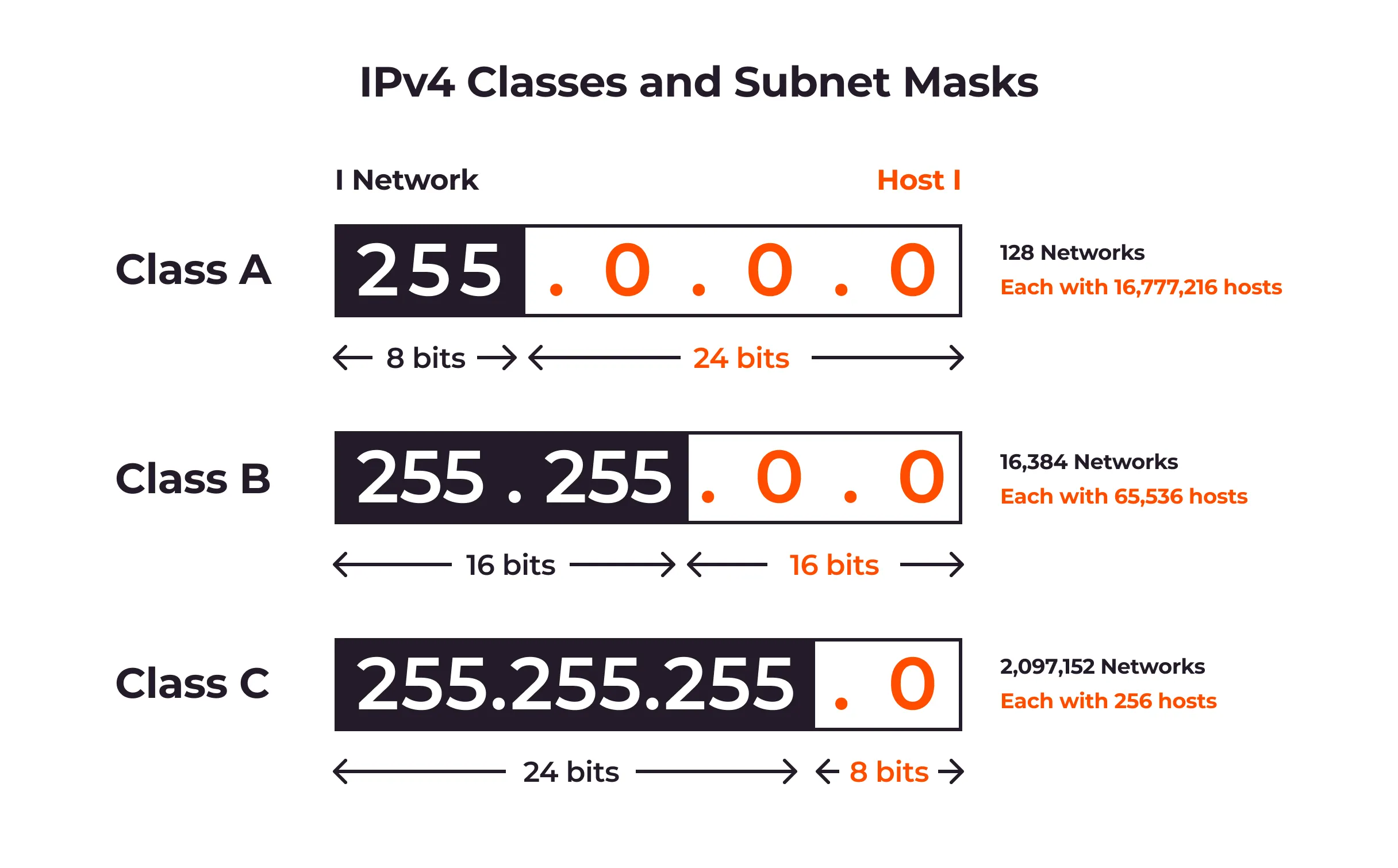
IPv4 Classes

Class IP Range Start bits Number of Networks Number of Hosts Total Address space
A 0.0.0.0 - 127.255.255.255 0 128(two reserved) 16777216 () 2147483648 ()
B 128.0.0.0 - 191.255.255.255 10 16384 () 65356 () 1073741824 ()
C 192.0.0.0 - 223.255.255.255 110 2097152 () 256 () 536870912 ()
D 234.0.0.0 - 239.255.255.255 1110
E 240.0.0.0 - 247.255.255.255 1111
Fundamental of Computer Systems: U19952-2023-2024
Canterbury Christ Church University

IPv4 Formatting

Class IP address Range Formatting
A 0.0.0.0 127.255.255.255 0NNNNNNN. HHHHHHHH.HHHHHHHH.HHHHHHHH​
B 128.0.0.0 191.255.255.255 10NNNNNN.NNNNNNNN.HHHHHHHH.HHHHHHHH​
C 192.0.0.0 223.255.255.255 110NNNNN.NNNNNNNN.NNNNNNNN.HHHHHHHH​
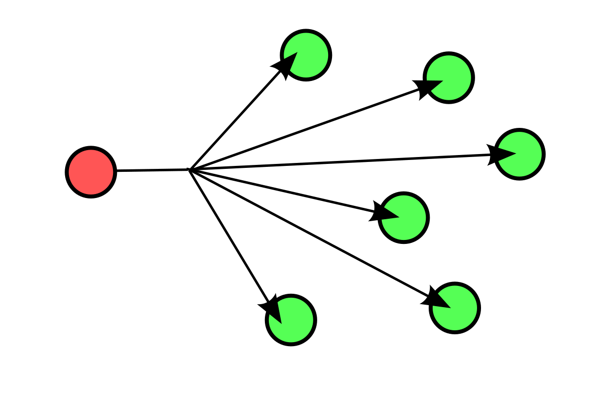
D 234.0.0.0 239.255.255.255 MULTICASTING
E 240.0.0.0 247.255.255.255 EXPERIMENTAL

Class D - A multicast (one-to-many) is different from a broadcast (one-to-al). Every device on a logical network must process a broadcast, whereas only devices configured to listen for a Class D address receive a multicast.

Class E - Class E addresses are reserved for experimental purposes and should not be used to address hosts or multicast groups.

Fundamental of Computer Systems: U19952-2023-2024
Canterbury Christ Church University

Loopback Address

IP address range 127.0.0.0 to 127.255.255.255 is reserved.​

This is for the loopback address network and local host.​

  • Allows for a device to send and receive its own data packet​

  • Allows for analysis like testing and debugging, or allowing routers to communicate in specific ways​

$ cat /etc/hosts

127.0.0.1 localhost
::1 localhost
127.0.0.2 vakare
::1 vakare
Fundamental of Computer Systems: U19952-2023-2024
Canterbury Christ Church University

IPv4 Addressing

What is this class is this address and its dotted decimal notation:​

11101101.11010010.01001111.00100011 ​ ​Class D​

​237.210.79.35

10100101.00111000.00010101.10000110​

Class B​
165.56.21.134​

00100011.10111101.00101111.10010100 Class A​

35.189.47.148​

11000000.10101000.00000001.10001000 Class C​

192.168.1.136​

Fundamental of Computer Systems: U19952-2023-2024
Canterbury Christ Church University

Netmask/CIDR

  • Netmasks defines how large a network can be, this help limit the number of devices that can connect to your network. i.e., the number of the available address

  • Can help distinguish between network and host within the IP address.

  • Classless Inter-Domain Routing (CIDR)/Netmask was designed by the Internet Engineering Task Force (IETF) to slow down the exhaustion of addresses and chaotic routing tables.​

  • CIDR (e.g., /32)is the number of the bit from the left

  • Size of Subnet Mask it's 32 bits

Fundamental of Computer Systems: U19952-2023-2024
Canterbury Christ Church University

Examples

IP Address​ Netmask​ Description​ Netmask Length or CIDR​
192.168.55.161​ 255.255.255.255​ Only applies to 192.168.55.161​ /32 (4 octets)
192.168.55.0​ 255.255.255.0​ Applies to the range 192.168.55.0-255​ /24
192.168.55.240​ 255.255.255.240​ Applies to the range 192.168.55.240-255​ /28
192.168.0.0​ 255.255.0.0​ Applies to the range 192.168.0-255.0-255​ /16

width:1OO% center

Fundamental of Computer Systems: U19952-2023-2024
Canterbury Christ Church University

Netmask - Subnetting

So lets look at the binary subnet mask, we can see that /## denotes the number of ones masked off which means only the addresses not masked are available to that network. ​

IP/CIDR​ Binary Mask​ Number of Hosts​
192.168.55.161/32​ 11111111.11111111.11111111.11111111​ 1
192.168.55.0/24​ 11111111.11111111.11111111.00000000 256
192.168.55.240/28​ 11111111.11111111.11111111.11110000​ 16
192.168.55.161/24​ 11111111.11111111.11111111.00000000​ 256
192.168.0.0/16​ 11111111.11111111.00000000.00000000​ 65536
192.168.2.1/29​ 11111111.11111111.11111111.11111000​ 8

Fundamental of Computer Systems: U19952-2023-2024
Canterbury Christ Church University

Calculating the CIDR

The IP addresses range is from 21.19.35.64 and 21.19.35.127. Find the CIDR block?​

CIDR block is 21.19.35.64/26

Fundamental of Computer Systems: U19952-2023-2024
Canterbury Christ Church University

Netmask - Subnetting

So lets look at the binary subnet mask, we can see that /## denotes the number of ones masked off which means only the addresses not masked are available to that network. ​

11101101.11010010.01001111.00100011 /11111111.11111111.11111111.11111111​

237.210.79.35/32

11000000.10101000.00000001.10001000 /11111111.11111111.11111111.00000000​

192.168.1.136/24​

11000000.01100101.00000101.00000000 /11111111.11111111.11100000.00000000​

192.101.5.0/19​

Fundamental of Computer Systems: U19952-2023-2024
Canterbury Christ Church University

Network Address (Start Address)

  • It is the address used to identify a specific network. It represents the beginning of a range of IP addresses assigned to devices (hosts) within that network.

  • The network address is obtained by performing a logical AND operation between an IP address and its corresponding subnet mask.

  • This operation effectively "masks out" the host portion of the IP address, leaving only the network portion intact

  • All host bits are 0

Fundamental of Computer Systems: U19952-2023-2024
Canterbury Christ Church University

Example

IP Address: 192.168.1.100
Subnet Mask: 255.255.255.0

  1. Convert IP Address to Binary: IP=11000000.10101000.00000001.01100100

  2. Convert Subnet Mask to Binary: SNM= 11111111.11111111.11111111.00000000

  3. Perform Logical AND Operation:

  4. Network Address: 192.168.1.0

Fundamental of Computer Systems: U19952-2023-2024
Canterbury Christ Church University

Broadcast Address (Final Address):

The broadcast address is used to send data packets to all devices within a specific network. It represents the end of the range of IP addresses assigned to devices within that network
width:1OO% center

Fundamental of Computer Systems: U19952-2023-2024
Canterbury Christ Church University

Example

  1. Invert Subnet Mask to get Wildcard Mask: 00000000.00000000.00000000.11111111

  2. Perform Logical OR Operation:


OR

=

Broadcast Address: 192.168.1.255

Fundamental of Computer Systems: U19952-2023-2024

TCP/IP stands for Transmission Control Protocol/Internet Protocol and is a suite of communication protocols used to interconnect network devices on the internet. TCP/IP and OSI are the most widely used communication networking protocols.​

![bg right:40% 100%](../../figures/physical.png)

## Specialised Devices 1 **Switches​** Switches connect and help to internally secure computers, printers, servers, and other devices to networks in homes or organisations​ ![width:1OO% height:90 center](../../figures/switch.png) **Access Points**​ Access points are switches that connect devices to networks without the use of cables ![width:1OO% height:100 center](../../figures/accesspoint.png.jpeg) --- ## Specialised Devices 1 Switches/Access Points identify a connected computer by its Media Access Control (MAC) address. ​ ![width:1OO% height:200px center](../../figures/MAC-Address.png) - MAC 12-digit hexadecimal numbers (48 bits in length) – MM:MM:MM:SS:SS:SS​ - M is the manufactor's id and S is the unique id per device - 00:0a:95:9d:68:16 this is the Network Interface Card (NIC) ---

Manages the mapping between logical addresses and physical addresses, for IP addresses, this is accomplished through Address Resolution Protocol or ARP​

## Specialised Devices 2 ![bg right:40% 100%](../../figures/router.png) **Routers​** - Connect networks to other networks and act as dispatchers. ​ - They analyse data to be sent across a network, choose the best routes for it, and send it on its way. ​ - Routers connect your home and business to the world and help protect information from outside security threats​ - Routers connect your home and business to the world and help protect information from outside security threats​ <!--Routers identify a connected computer by is network assigned​ Internet Protocol (IP) address. ​ IPv4 addresses are usually represented in dot-decimal notation, ​ consisting of four decimal numbers, each ranging from 0 to 255 ​ ​ xxx.xxx.xxx.xxx -> 192.168.1.0​

For example, say you are ordering something from an online store. ​ These transactions are typically handled in a secure transmission which means ​ that the data passing between the “store” or the Website Application will transmit ​ encrypted data to the Presentation layer that will need to be decrypted and processed​

All of those interactive applications provide a set of services that allow the application layer to supply data to and receive data from the Presentation layer​

Encapsulation and Decapsulation. These terms refer to how data is moved through the layers from top to bottom when sending and from bottom to top when receiving. As the data is handed from layer to layer, each layer adds the information it requires to accomplish its goal before the complete datagram is converted to 1s and 0s and sent across the wire. For example: Layer 4 will add a TCP header which would include a Source and Destination port Layer 3 will add an IP header which would include a Source and Destination IP address Layer 2 would add an Ethernet header which would include a Source and Destination MAC address

<p align=center> 192.168.0.1 </p> <p align=center> 11000000.10101000.00000000.00000001 </p>